This Month's Featured Shaking Test Video
On around the 15th of each month, one past E-Defense shaking table experiment video is selected from the archives and featured with detailed commentary.
-
E201601 : Seismic Performance Evaluation Tests of Wooden Houses and Carports in Recent Large Earthquakes
Explanation
The Importance of an “Earthquake-Resistant Home”
When a disaster strikes, everyone thinks, “I’ll be fine,” “I won’t die,” or, “Somehow, things will work out.” This is a psychological trait known as the “normalcy bias,” in which people tend to underestimate risks even when their own lives are in danger due to natural disasters or other situations. However, in reality, homes with poor seismic resistance will collapse, and even if a building doesn’t collapse, residents who are unable to escape in time may suffer serious injuries inside a damaged structure. Once this happens, it’s too late to do anything about it. So, what should we do? The answer is simple: build a home that you can truly say, “It’s really safe.”
Improving the Seismic Performance of Newly Built Homes
In Japan, a country prone to earthquakes, improving seismic performance is the first priority. Under the current Building Standards Act, seismic standards for wood-frame homes have been strictly enforced, and it is generally considered that if a home satisfies the “New Seismic Standards,” the risk of collapse during major earthquakes in recent years is quite low. However, is it enough simply to avoid collapse? Of course, saving lives is the most important priority, but if a building sustains significant damage, the risk of serious injury inside the home increases. Survivors are then faced with the painful reality of having to pay off their mortgage while also covering the costs to repair their damaged home—a burden they must bear precisely because they survived.
Therefore, beyond the structural frame itself, the development focused on ensuring that all residential components—including interior finishes, exterior finishes, roofs, openings, and home fixtures—would sustain no damage during a major earthquake, allowing residents to continue daily life as usual afterward. The solutions resulting from the pursuit of “seismic performance that exceeds the Building Standards Act” are “Double Seismic Resistance Homes” and “Seismic Isolation Homes.”
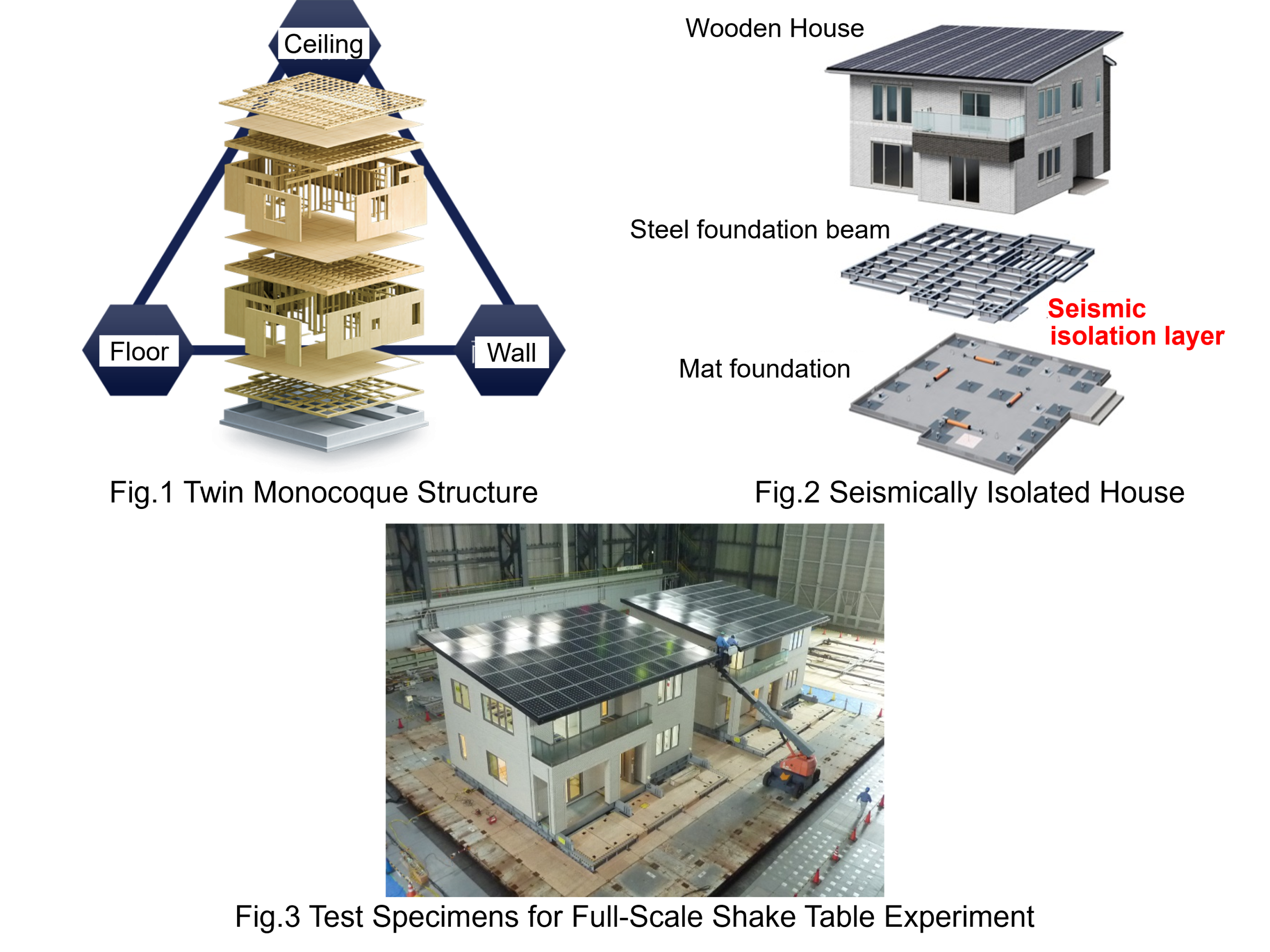
The “Double Seismic Resistance homes (Seismic Resistance Grade 5)” are designed to provide twice the strength required by the Building Standards Act. By firmly joining high-strength panelized exterior walls, floors, and ceilings with metal fittings, the entire house forms a box-shaped hexahedron (twin monocoque structure, Fig. 1), minimizing the building’s deformation in response to forces from any direction. Furthermore, high-strength interior walls called “special mid-ply walls” are strategically installed to reduce building torsion and prevent damage to structural components. In other words, this system provides the “strength to withstand and contain” seismic forces with structural integrity that exceeds the forces themselves.
In contrast, the “seismic isolation houses” are designed with a seismic isolation device (seismic isolation layer) inserted between the foundation and structure (Fig. 2). During earthquakes, the seismic isolation device supports the weight of the building while undergoing horizontal deformation. This dissipates seismic forces, minimizing deformation of the building structure itself, and simultaneously transforms strong shaking into gentle swaying, thereby preventing furniture and fixtures inside the house from toppling over or scattering. This can be described as the device having the “strength to deflect and suppress” seismic forces.
Real-Scale Wooden House Seismic Testing Using the E-Defense Shaking Table
In research and development of homes with double seismic resistance and seismic isolation, the world's largest shake table, E-Defense, was used to repeatedly subject a “realistic building” which faithfully reproduced roofing materials, exterior walls, interior walls, furniture, appliances, and even the interiors of storage units while accounting for living loads to seismic excitation. This allowed the verification of the “true seismic performance” (Fig. 3).
Here is a video showing the shaking table test of a double seismic resistance house (2606_MPV1). As observed, the house exhibits extremely high rigidity, and almost no deformation occurred during the shaking. Even when subjected to the massive seismic motions observed during the 1995 Southern Hyogo Prefecture Earthquake and the 2016 Kumamoto Earthquake, the building remained undamaged, and no noticeable damage was observed on the gypsum board and wallpaper.
Furthermore, experiments were conducted simultaneously on a house meeting the performance requirements of the Building Standards Act (Seismic Resistance Grade 1) and a seismic isolation house. When subjected to repeated earthquake motions including records from major observed earthquakes such as the Southern Hyogo Prefecture Earthquake and the Kumamoto Earthquake, the first floor of the Seismic Resistance Grade 1 house suffered collapse, while no damage was observed in the seismic isolation house (2606_MPV2).
Summary
As a country prone to earthquakes, Japan faces the risk of experiencing unprecedented strong earthquakes. However, when significant disasters do not occur for a while, public awareness of disaster risks tends to wane. There is a Japanese proverb saying, “Disasters strike when people forget about them.” As this proverb suggests, when awareness has waned, a sudden major disaster can strike. To protect your lives and properties against such a disaster, how strong of a home do you actually need? Taking this opportunity, please consider about it.
Responsibility in writing: Takahashi
Detailed experimental data is available in ASEBI.
DOI: https://doi.org/10.17598/NIED.0020-E201601Last Updated:2026/06/18
-
Test Preparation : Get to the secret of how to make efficient use of the E-Defense shaking table!
Explanation
The size of test specimens used in experiments conducted on the E-Defense shake table varies widely, ranging from full-scale buildings to small- and medium-sized equipment. However, if full-scale buildings are constructed on the shake table, the construction process itself would take several months to a year, limiting the number of experiments to only one or two per year. Under these circumstances, it cannot be said that the E-Defense shake table, a globally rare experimental facility, is being utilized effectively. In reality, over the 21 years from the start of E-Defense shake table operations in fiscal year 2005 through the end of fiscal year 2025, a total of 136 experiments has been conducted (43 by the National Research Institute for Earth Science and Disaster Resilience (NIED), 35 as joint research between NIED and external organizations, and 58 as facility-use experiments by external organizations). How have so many experiments been conducted? This month, we’ll take a break from showcasing shaking table experiment videos and explore the secret behind this.
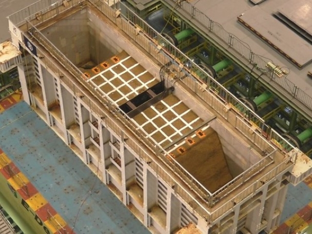
Test specimens are generally constructed outdoors, with the exception of those that are sensitive to weather changes. For example, see the construction process of the building in “E202003: Holistic Seismic Assessment of Critical Buildings with Due Consideration of Non-Structural Component and Equipment” (2605_MPV1 ). The steel members manufactured at the steel plant were transported to the site of the E-Defense facility. Just as in the construction of an actual building, temporary scaffolding was set up around the structure, and heavy construction machinery was used to assemble the steel framework. Floor formwork was installed (the video above shows up to this stage) followed by the placement of reinforcing bars and the pouring of concrete. Afterward, the concrete was cured until it hardened and achieved sufficient strength. The primary reason why experiments using full-scale buildings are essential is to eliminate the effects of the size effect (a phenomenon in which strength decreases as the size of a building or its structural members becomes larger). However, since a building’s performance is also influenced by its construction process, another key reason is the ability to evaluate and verify performance under conditions that are closer to those of an actual building.
The building is now constructed. So, how is this building placed onto the E-Defense shake table?
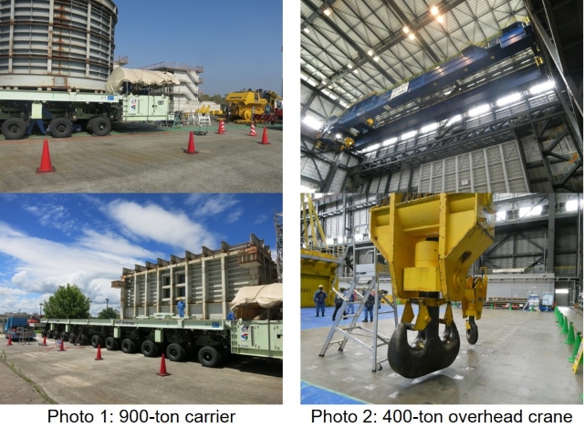
Buildings weighing tens to hundreds of tons are transported into the “Experimental Building,” where the E-Defense shake table is located, using a special carrier truck (Photo 1; maximum load capacity: 900 tons). A table mounted on the numerous tires of this truck moves up and down by using hydraulic jacks. The building is constructed on the platform, creating enough space to insert the carrier truck underneath the building. By driving this truck beneath the building and lifting the table higher than the platform, the building is lifted off the platform and placed onto the truck’s table. By driving the truck slowly in this state, it is possible to transport the building into the Experimental Building. See the actual transport process below (2605_MPV2 ). The structure being transported in this video is the building used in the “E202002: Experiment of Evaluation of Yield Point and Attenuation of 5-story RC Construction Building / Medium-rise RC Construction Building” experiment. This building was constructed on the six inverted T-shaped concrete blocks positioned on the left side at the start of the video. The height of the large doors in the Experimental Building is 20 meters, which should provide a clear sense of the size of this test specimen.
The structure brought into the Experiment Building is lifted using the two overhead cranes (Photo 2; nominal capacity: 400 tons) equipped in the E-Defense Experiment Building and placed on the shake table. See the situation where the structure for the “E-Defense Experiment E201806: E-Defense Experiment to verify the Function of 3-story Wooden Building including Underground Piping Equipment” is being placed on the shake table (2605_MPV3 ). As shown, a building is being placed on the shake table piece by piece. The shake table has holes for bolts, and holes for bolts are also drilled in the building base at the corresponding positions. The holes in the shake table and the building are aligned, bolts are inserted, and the shake table and the building are bolted together. This completes the experimental setup.
In this method, by constructing the building off the shake table and placing it on the table only when conducting experiments, it is possible to significantly reduce the duration of shake table occupancy per experiment (typically ranging from a few days to about three months per experiment). Through the efficient operation of this experimental facility, our goal is to contribute to disaster mitigation, and the enhancement of societal resilience - not only through the research of NIED but also by making the E-Defense shake table available to a wider range of researchers. Thank you kindly for your continued support.
Responsibility in writing: KawamataLast Updated:2026/05/15
-
E201505 : Shaking Table Experiment to verify Monitoring Technology of Earthquake-induced Damage along Pile Foundation
Explanation
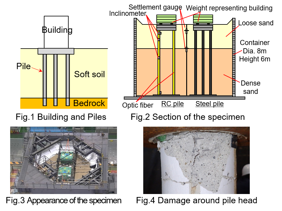
If soil beneath a building is soft and lacks sufficient strength relative to the building’s weight, the building may sink or tilt. Therefore, countermeasures are taken by either increasing the soil’s strength (soil improvement) or selecting an appropriate foundation. When the layer of soft soil beneath the building is thick, one of the most typical solutions involves driving piles—vertical columns—into the soil until they reach bedrock (Fig. 1).
When an earthquake occurs, the ground deforms laterally, causing horizontal forces to act on the piles, and the building’s shaking during the earthquake generates significant horizontal inertial forces that act on the pile cap. During a strong earthquake, the horizontal forces acting on the piles increase, leading to concrete crushing, tensile cracking, yielding, and buckling, resulting in failure of the piles. While it is obvious that significant damage has occurred along the piles when the significant settlement or tilting of the building supported by them occurs due to the loss of pile strength, there are also numerous reported cases where significant damage to the piles has occurred even when the building itself shows no noticeable damage. For example, during the demolition of a building, when the piles were excavated, it was discovered that significant damage had occurred to the piles during past earthquakes. Although the building had been used for decades as if nothing had happened, there was a risk that significant damage would have occurred if another major earthquake had struck. Therefore, the degree of damage to the piles supporting a building can be critical to its residual seismic performance and whether it can continue to be used. However, because piles are buried underground, it is not possible to determine the degree of damage through visual inspection.
Based on the above, as part of a national project, “Special Project for Reducing Vulnerability in Urban Areas”, E-Defense experiments were conducted in collaboration with the Disaster Prevention Research Institute at Kyoto University and Taisei Corporation to develop and validate monitoring technologies for assessing the degree of damage to piles due to earthquakes.
Two types of piles—steel piles and reinforced concrete (RC) piles—were installed inside a cylindrical soil box with a diameter of 8 m and a height of 6 m, and sand was poured around them. After the sand was leveled to the specified height, weights simulating a building were placed on top (Figs. 2 and 3). To detect earthquake-induced damage, various types of sensors were installed along the RC piles. Earthquake motions were applied to this test specimen using an E-Defense shake table (E201505_151020_4), and the measurement values from the various sensors were carefully verified.
Since the experimental videos only show the portion above ground surface, it was not possible to visually confirm any damage. After the experiment was completed, the soil around the pile was removed for damage inspection, and concrete spalling was observed at the pile top (Fig. 4). Among the various types of sensors installed along the RC pile, the optic fiber sensor successfully detected the significant strain corresponding to this concrete spalling. Based on the above, it was confirmed that selecting the appropriate sensor has the potential to evaluate damage in the invisible underground sections. On the other hand, since this method requires the optical fiber sensor to be installed directly on the pile, challenges remain to be resolved before practical implementation and widespread adoption, such as methods for installing them on existing piles. Efforts will continue to develop and verify better methods, including considerations for cost and installation methods.
Responsibility in writing: Kawamata
Detailed experimental data is available in ASEBI.
DOI: https://doi.org/10.17598/NIED.0020-E201505Last Updated:2026/04/17
-
E201303 : Experimental Study on Seismic Measures for Steel Frame Buildings damaged by Past Earthquakes
Explanation
During the 1995 Southern Hyogo Prefecture Earthquake, instances of beam failure at beam-column joints in steel-framed buildings were observed for the first time in Japan. Buildings suffering such damage often exhibit minimal post-earthquake tilting and little visible damage to exterior cladding, making it difficult to detect joint damage or failure during post-earthquake visual inspections. However, the beam-column joints are structurally critical components, and their damage significantly impacts the overall safety of the building. Therefore, technology is needed to detect this type of damage, which is difficult to identify visually after an earthquake, and to assess the building's integrity. This research conducted full-scale shake table tests on steel buildings to understand the damage that would occur if a steel-framed building with damaged beam-column joints were subjected to another major earthquake, and to develop technology for estimating the integrity of buildings damaged in a major earthquake.
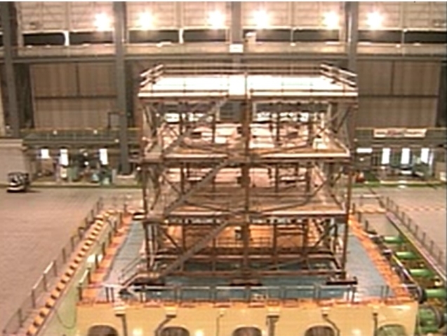
For the experimental planning, steel-framed buildings damaged in the Southern Hyogo Prefecture Earthquake were investigated, and three-story steel-framed buildings were selected as the research subjects. The test buildings were designed in accordance with the 1981 seismic regulations, simulating office buildings constructed within Kobe City.
An experimental procedure was planned for buildings that experienced beam-column joint failure during the Southern Hyogo Prefecture Earthquake, simulating a scenario where they encounter a major earthquake. In the experiment, undamaged steel-framed buildings were first subjected to the assumed major earthquake ground motion for comparison. Subsequently, the ground motion observed during the Southern Hyogo Prefecture Earthquake was applied to the beam-column joints, gradually increasing in intensity until failure occurred. Following the failure at the beam-column joint, the simulated major earthquake motion was reapplied. The seismic motion from the Southern Hyogo Prefecture Earthquake used the JR Takatori record. The simulated major earthquake motion was created based on the anticipated shaking in Kobe City during a Nankai Trough earthquake. The measured seismic intensity for the JR Takatori recording and the simulated major earthquake motion was 6.3 and 5.4, respectively.
In the experiment, the acceleration amplitude of the JR Takatori motion was reduced to 40%, 60%, and 80% for input. As the experiment progressed and deformation repeated, the beam-column joint failed in the experiment using 100% of the JR Takatori input (whole building shaking: E201303_131010_08_31 , joint failure: E201303_131010_08_17 ). Subsequently, the assumed major seismic motion was input at intensities of 50%, 100%, and 150% (building sway at 150% input: E201303_131015_10_31 ).
The building inclination measured after each seismic input remained minor, confirming that such damage is difficult to detect through visual inspection of the exterior. Although inputting large seismic motions after the beam-column joint failure did not lead to major events like building collapse in this experiment, the magnitude of seismic deformation approximately doubled before and after failure. This indicates a potential risk of hazardous damage, such as falling exterior cladding. Furthermore, technologies for detecting damage to beam-column joints were investigated. It was confirmed that the building's natural period changes distinctly due to joint failure. Additionally, it was possible to measure the building's natural period from both the micro-tremor inherent to the structure and from vibrations applied to the building using small-scale machinery.
This research was conducted as a joint research project between Hyogo Prefecture and the National Research Institute for Earth Science and Disaster Resilience, and as a collaborative research project between Hyogo Prefecture and Kobe University. Sincere thanks to all involved in this effort.
Responsibility in writing: Fujiwara
Detailed experimental data is available in ASEBI.
DOI: https://doi.org/10.17598/NIED.0020-E201303
A detailed report on this experiment is also available on the Hyogo Prefecture website.
https://web.pref.hyogo.lg.jp/kk41/e-defenseh25.html
Last Updated:2026/03/15
-
E202102 : Full-scale Shaking Table Test of Seismic Reinforced Joints for Water Pipelines
Explanation
The 2024 Noto Peninsula Earthquake caused widespread failure of water supply and sewerage systems, severely impacting daily life in the affected areas and leading to long-term recovery and reconstruction efforts. Furthermore, on the 28th of the same month, an extensive road collapse occurred in Yashio City, Saitama Prefecture, caused by damage to buried sewer pipes. As of February 2026, one year later, restoration work is still ongoing. In January 2026, it was reported that the Ministry of Land, Infrastructure, Transport and Tourism plans to revise seismic standards, focusing primarily on water pipelines connected to disaster bases such as medical facilities and evacuation centers, with the aim of enhancing seismic reinforcement and addressing aging infrastructure.
The proportion of earthquake-resistant pipelines within the primary water supply network stood at a low 42.3% as of the end of fiscal year 2022. Promptly advancing seismic reinforcement of underground pipelines is an urgent priority to ensure stable water supply during future disasters and establish a system capable of rapid restoration. Examining damage to buried pipelines in past earthquakes reveals that, for example, in the 2011 Tohoku Region Pacific Ocean offshore Earthquake, approximately 70% of the damage to ductile iron pipes, a representative water supply pipe material, was caused by pipes disconnecting at their joints. Therefore, it is apparent that reinforcing pipe joints to prevent disconnection is a highly effective reinforcement method. Based on the above, as part of a joint research project with Taisei Kiko Co., Ltd. and Kanazawa University, a large-scale E-Defense shaking table experiment was conducted on a water supply pipeline using full-scale ductile iron pipes buried in the ground.
In the experiment, water pipeline specimens with unreinforced joints and earthquake-resistant reinforced joints were installed within sloping ground. As the seismic reinforcement methods for the joints, techniques capable of continuously supplying water to the surrounding area without installing bypass pipelines were selected. By applying seismic forces to these test specimens using the E-Defense Shaking Table, the slope was intentionally collapsed, inducing significant ground displacement around the joint areas (E202102_211026_1). As a result, the unreinforced joint completely disconnected, allowing surrounding soil to flow into the pipe and completely losing its function as a lifeline (E202102_211026_3). In contrast, the earthquake-resistant joint remained securely attached without detachment, and no soil inflow into the pipe was observed (e.g., pipe interior footage using earthquake-resistant reinforcement fittings, E202102_211026_2). After the experiment, when water pressure was applied to the pipe, no pressure drop or leakage due to joint damage was detected, confirming the pipe maintained its functionality as a water supply line.
This experimental research aims to contribute to the promotion of earthquake-resistant reinforcement for water supply pipelines. Furthermore, special thanks are expressed to the Osaka City Waterworks Bureau, Okayama City Waterworks Bureau, Kobe City Waterworks Bureau, and other related organizations that participated in and cooperated with the experiments.
Responsibility in writing: Kawamata
Detailed experimental data is available in ASEBI.
DOI: https://doi.org/10.17598/NIED.0020-E202102
Last Updated:2026/02/16
-
E200505 : E-Defense Experiments on Existing Non-compliant Wooden Houses with and without Reinforcement
Explanation
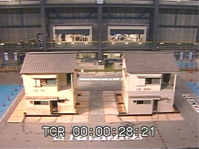
The two test specimens used in this experiment were actual 32-year-old wooden houses (wooden post-and-beam construction) built with identical structural specifications and floor plans.
These two houses were carefully disassembled, their components transported, and then reassembled on the E-Defense shake table, effectively “relocating” them (the depth direction in the photo is the X-axis, the width direction is the Y-axis). One building served as the “unreinforced test specimen” (right in photo), while the other was the “seismic-reinforced test specimen” (left in photo), reinforced by adding metal brackets at beam-column joints, structural plywood, and diagonal bracing. The evaluation scores (*1) for the “unreinforced test specimen” were 1.17 (X-direction) and 0.50 (Y-direction) for the first floor, and 1.23 (X-direction) and 0.85 (Y-direction) for the second floor. In contrast, the seismic performance scores for the “seismic-reinforced test specimen” were 1.97 (X-direction) and 1.84 (Y-direction) for the first floor, and 1.94 (X-direction) and 2.01 (Y-direction) for the second floor, indicating a significant improvement in seismic performance.
The "unreinforced test specimen" completely collapsed when subjected to seismic motion equivalent to seismic intensity 7 observed at JR Takatori Station during the 1995 Southern Hyogo Prefecture Earthquake (E200505_051121).
This phenomenon of first-floor collapse in houses occurred frequently during the 1995 Southern Hyogo Prefecture Earthquake and has also been observed in the 2024 Noto Peninsula Earthquake, occurring approximately 30 years later. The “seismic-reinforced test specimen” avoided collapse, but damage was observed, including lift-off and detachment of structural plywood, separation of bracing, and loosening of metal fittings. After evaluating the damage and recalculating the score, the first floor achieved a score of 0.93 (Y-direction).
After removing the collapsed “unreinforced specimen,” when the damaged “seismic-reinforced test specimen” was again subjected to seismic excitation using the ground motion observed at JR Takatori Station, it completely collapsed, just like the “unreinforced specimen” (E200505_051124).
In recent major earthquakes, multiple strong seismic motions have been observed. Damage to buildings can be accumulated through these multiple motions, so it is important to accurately assess the seismic performance of your home and simulate responses appropriate for potential scenarios.
Responsibility in writing: Kawamata
Detailed experimental data is available in ASEBI.
DOI: https://doi.org/10.17598/NIED.0020-E200505
※1: The score is calculated as the ratio of actual seismic resistance to required seismic resistance. A score of 1.0 indicates the minimum seismic performance required to meet the new seismic standards, while a score of 1.5 or higher is evaluated as “will not collapse.” Conversely, a score below 1.0 indicates a high possibility of collapse.
Last Updated:2026/01/15